
Protocol Modbus sangat banyak di gunakan di perangkat-perangkat yang ada di industri. Hal ini saya sadari ketika bergabung dengan group belajar modbus yang di mentoring oleh pak Fuad Hasan.
Contoh perangkat yang punya protokol modbus adalah power meter PM2120, PZEM-016 dan Perangkat-perangkat lain nya yang biasa di pakai di wilayah industri.
Pertanyaan yang timbul adalah apakah kita bisa jadikan Arduino sebagai client dari Modbus itu sendiri? sehingga nanti nya kita bisa menghubungkan Arduino dengan banyak arduino melaui protokol ini? Jawaban nya bisa. Yuk kita bahasa bagaimana cara pembuatan nya.

Library Modbus
Untuk library modbus Arduino client ini, teman-teman bisa download di link berikut ini, atau cukup tekan tombol merah di bawah ini
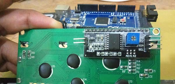
setelah didownload dan di add di library Arduino kita, yuk kita coba experiment mengirimkan data ADC 16bit dari ADS1115 melalui protokol modbus
berikut Pemrograman nya
#include <Wire.h>
#include <LiquidCrystal_I2C.h>
#include <Adafruit_ADS1015.h>
LiquidCrystal_I2C lcd(16, 2);
Adafruit_ADS1115 ads; /* Use this for the 16-bit version */int16_t adc0, adc1, adc2, adc3;
int16_t adc0MAX, adc0MIN;
float voltage = 0.0;
String DATA;
String line1, line2;
#include &amp;lt;SimpleModbusSlave.h&amp;gt;
/*
SimpleModbusSlaveV10 supports function 3, 6 &amp;amp; 16.
This example code will receive the adc ch0 value from the arduino master.
It will then use this value to adjust the brightness of the led on pin 9.
The value received from the master will be stored in address 1 in its own
address space namely holdingRegs[].
In addition to this the slaves own adc ch0 value will be stored in
address 0 in its own address space holdingRegs[] for the master to
be read. The master will use this value to alter the brightness of its
own led connected to pin 9.
The modbus_update() method updates the holdingRegs register array and checks
communication.
Note:
The Arduino serial ring buffer is 64 bytes or 32 registers.
Most of the time you will connect the arduino to a master via serial
using a MAX485 or similar.
In a function 3 request the master will attempt to read from your
slave and since 5 bytes is already used for ID, FUNCTION, NO OF BYTES
and two BYTES CRC the master can only request 58 bytes or 29 registers.
In a function 16 request the master will attempt to write to your
slave and since a 9 bytes is already used for ID, FUNCTION, ADDRESS,
NO OF REGISTERS, NO OF BYTES and two BYTES CRC the master can only write
54 bytes or 27 registers.
Using a USB to Serial converter the maximum bytes you can send is
limited to its internal buffer which differs between manufactures.
*/
#define LED 9
// Using the enum instruction allows for an easy method for adding and
// removing registers. Doing it this way saves you #defining the size
// of your slaves register array each time you want to add more registers
// and at a glimpse informs you of your slaves register layout.
//////////////// registers of your slave ///////////////////
enum
{
// just add or remove registers and your good to go...
// The first register starts at address 0
ADC_VAL,
PWM_VAL,
HOLDING_REGS_SIZE // leave this one
// total number of registers for function 3 and 16 share the same register array
// i.e. the same address space
};
unsigned int holdingRegs[HOLDING_REGS_SIZE]; // function 3 and 16 register array
////////////////////////////////////////////////////////////
void setup()
{
lcd.autoAddress();
lcd.begin();
// ADS1015 ADS1115
// ------- -------
ads.setGain(GAIN_TWOTHIRDS); // 2/3x gain +/- 6.144V 1 bit = 3mV 0.1875mV (default)
//ads.setGain(GAIN_ONE); // 1x gain +/- 4.096V 1 bit = 2mV 0.125mV
// ads.setGain(GAIN_TWO); // 2x gain +/- 2.048V 1 bit = 1mV 0.0625mV
// ads.setGain(GAIN_FOUR); // 4x gain +/- 1.024V 1 bit = 0.5mV 0.03125mV
// ads.setGain(GAIN_EIGHT); // 8x gain +/- 0.512V 1 bit = 0.25mV 0.015625mV
// ads.setGain(GAIN_SIXTEEN); // 16x gain +/- 0.256V 1 bit = 0.125mV 0.0078125mV
ads.begin();
adc0MIN = adc0;
adc0MIN = adc0;
/* parameters(HardwareSerial* SerialPort,
long baudrate,
unsigned char byteFormat,
unsigned char ID,
unsigned char transmit enable pin,
unsigned int holding registers size,
unsigned int* holding register array)
*/
/* Valid modbus byte formats are:
SERIAL_8N2: 1 start bit, 8 data bits, 2 stop bits
SERIAL_8E1: 1 start bit, 8 data bits, 1 Even parity bit, 1 stop bit
SERIAL_8O1: 1 start bit, 8 data bits, 1 Odd parity bit, 1 stop bit
You can obviously use SERIAL_8N1 but this does not adhere to the
Modbus specifications. That said, I have tested the SERIAL_8N1 option
on various commercial masters and slaves that were suppose to adhere
to this specification and was always able to communicate... Go figure.
These byte formats are already defined in the Arduino global name space.
*/
modbus_configure(&amp;amp;Serial, 9600, SERIAL_8N2, 1, 4, HOLDING_REGS_SIZE, holdingRegs);
// modbus_update_comms(baud, byteFormat, id) is not needed but allows for easy update of the
// port variables and slave id dynamically in any function.
modbus_update_comms(9600, SERIAL_8N2, 1);
pinMode(LED, OUTPUT);
}
void loop()
{
// modbus_update() is the only method used in loop(). It returns the total error
// count since the slave started. You don't have to use it but it's useful
// for fault finding by the modbus master.
modbus_update();
adc0 = ads.readADC_SingleEnded(0);
adc1 = ads.readADC_SingleEnded(1);
adc2 = ads.readADC_SingleEnded(2);
adc3 = ads.readADC_SingleEnded(3);
holdingRegs[0] = adc0;// update data to be read by the master
holdingRegs[1] = adc1;
holdingRegs[2] = adc2;
holdingRegs[3] = adc3;
lcd.setCursor(0, 0);
lcd.print(adc0);
delay(1000);
/* Note:
The use of the enum instruction is not needed. You could set a maximum allowable
size for holdinRegs[] by defining HOLDING_REGS_SIZE using a constant and then access
holdingRegs[] by "Index" addressing.
I.e.
holdingRegs[0] = analogRead(A0);
analogWrite(LED, holdingRegs[1]/4);
*/}
Configurasi Modbus
Untuk program di atas, hal yang penting untuk di lihat adalah sebagai berikut,
modbus_configure(&amp;amp;amp;Serial, 9600, SERIAL_8N2, 1, 4, HOLDING_REGS_SIZE, holdingRegs); // modbus_update_comms(baud, byteFormat, id) is not needed but allows for easy update of the // port variables and slave id dynamically in any function. modbus_update_comms(9600, SERIAL_8N2, 1);
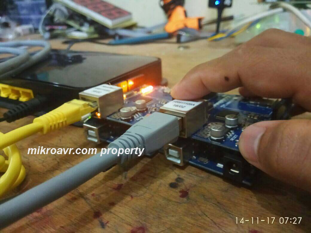
- Pin yang terhubung ke modul RS485 adalah pin Serial pada arduino, jika menggunakan arduino, bisa pin serial di rubah ke Serial1 atau Serial2 atau Serial3. tinggal di sesuaikan di modbus_configure
- baudrate nya adalah 9600, ID = 1, dan pin Enable rs485 nya terhubung ke pin D4
- dan yang terakhir adalah addres dari setiap data, di program di atas, data adc0 di address 0, data adc1 di addres 1, data adc2 di address 2 dan adc3 ada di address 3
Uji data Modbus dengan modbus scan

Program di atas menunjukkan bahwa data ads1115 16bit sudah berhasil di kirim ke modbus scan.
Modbus scan adalah sebuah software Komputer untuk membaca data modbus dari client ( perangkat)
Semoga tulisan sederhana di atas bermanfaat bagi teman-teman, jika ingin bertanya tentang modbus lebih lanjut, boleh visit di blog modbus nya SIMOR,
check di blog berikut http://puaks.blogspot.com/ atau bisa chat langsung orang nya dengan tekan tombol di bawah ini


